|
|
|
|
WHAT ARE THE EFFECTS OF OBSTRUCTION ?
Computer generated images, drawings and texts are property of the author and may not be reproduced or used without consent
What is obstruction ?
The obstruction of a reflector is represented by its secondary mirror (and its support) which stops the central part of the light beam.
The amount of obstruction can vary from one telescope to another. It depends on its optical principle (Newtonian, SCT, etc.) and on choices of construction linked to the desired field of full light (ie without vigneting). The value of obstruction usually varies, in percentage of the diameter of the telescope, from 15 % for 35 %. Specialized instruments, like the ones dedicated to deep-sky astrophotography, can be obstructed more than 40 %.
In the aim of presenting more flattering numbers, some companies give the value of the obstruction of their reflectors in percentage of the collecting surface of the instrument instead of the percentage of its diameter. The surface obstruction can be deducted from the diameter obstruction by calculating its square. Example: a diameter obstruction of 20 % (40 mm on a 200 mm) corresponds to a surface obstruction of 4 % (square of 0.20). Conversely, a surface obstruction of 10 % corresponds to a diameter obstruction of 32 % (square root of 0.1). Some other companies give the diameter of the secondary mirror instead of the diameter of its support, while it is obvious that what counts is the latter.
The effects of obstruction are of two types: the amount of light received by the instrument is decreased, and the contrast of the image is modified.
The decrease of light received by the instrument corresponds to its surface obstruction. A telescope with an obstruction of 20 % loses 4 % of light, while an obstruction of 33 % leads to a loss of light of 11 %. It is clear that, even with large obstructions, the loss of light is small: a 250 mm reflector obstructed at 34 % receives the same amount of light than an unobstructed 235 mm telescope.
What are the effects of obstruction on the Airy pattern ?
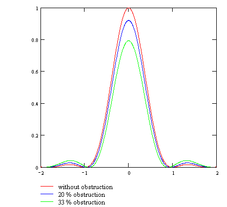
The presence of obstruction modifies the diffraction pattern (Airy pattern) of a star given by the instrument. This figure, visible at high magnification, is composed of a central disk (false disk) surrounded by rings of decreasing brightness (figures below). The obstruction has the effect of decreasing the amount of light which contributes to the disk (whose diameter is slightly decreased), for the benefit of the rings. Figures below show the appearance of the Airy pattern for obstructions of 0 %, 20 % and 33 %.
|
|
|
|
Even if the modification of the Airy pattern seems considerable (the images above are displayed in logarithmic scale to fit the human vision), the effect applies to small levels of light, as show the profiles below: from 0 % to 33 % of obstruction, the maximum intensity of the first diffraction ring increases from 1.7 % to 5.4 % of the maximum intensity of the central disk. It is untrue to claim that in presence of obstruction, the disk merge with the first ring.

What are the effects of obstruction on the contrast ?
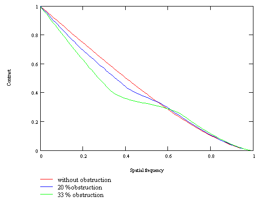
The MTF curve below (see What is a MTF curve ?) shows that the contrast is modified in a complex manner. Indeed it decreases in comparison with the unobstructed instrument, but only in low and medium frequencies (left part of the curve). On the other hand, in the high frequencies, the contrast is not decreased, it is even slightly increased.

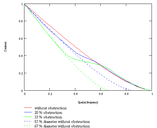
The figure below gives the curves corresponding to reflectors obstructed at 20 % and 33 %. The extension of the left part of each curve shows to which unobstructed telescope the reflector is equivalent in contrast in the low frequencies. It appears that in these frequencies a reflector with an obstruction of 33 % is equivalent to an unobstructed instrument whose diameter is 33 % less (170 mm for 250 mm). A reflector with an obstruction of 20 % is equivalent to an unobstructed instrument whose diameter is 15 % less (210 mm for 250 mm).

An empirical rule deducted from these results is that an instrument of diameter D and obstruction d, in the low frequencies, is equivalent to an unobstructed instrument whose effective diameter Deff is:
Deff = D - d
(this rule is slightly pessimistic for small obstructions).
To examine the effects on the resolution power of the telescope, we must consider two cases:
1) high contrast structures: Moon, double stars, Cassini division, shadow of a ring or a satellite, edge of a planet. Since the resolution limit is placed in the right part of the MTF curve (see What is high resolution ?), it is not modified by obstruction.
2) low contrast structures: surfaces of Mars, Jupiter and Saturn. The resolution limit is situated at a lower frequency than in the previous case. For details of very low contrast, this limit can be placed before the intersection of the curves. In this case, it is lower for the obstructed instrument. Then, as for the contrast in low frequencies, the resolution of the instrument is equivalent to those of an unobstructed telescope whose diameter is Deff.
The fact that the resolution limit is to the left or to the right of the intersection of the curves (and therefore the fact that there is a reduction of the resolution or not) depends on the intrinsic contrast of the object (which can vary according to the wavelenght: Jupiter has more contrast in the blue than in the red). It also depends on the technique: CCD, photography or visual observation (the contrast threshold differs: about 2 % for the eye in good lighting conditions, probably 0.5 % in CCD). No general rule can be given about the loss of resolution on low contrast surfaces. Nevertheless, the effective resolution is at least the resolution of an unobstructed instrument of diameter Deff.
These results are valid only if the instrument is optically good and properly collimated. If it is not the case, the MTF curve is squashed, the resolution limit is lowered and the loss of resolution affects all the objects, including high contrast objects like the Moon. But in this situation, can we still talk about high resolution ?
A spider, although it creates diffraction spikes on bright stars, has no visible influence on the contrast of the lunar and planetary images. For high resolution, it is therefore not necessary to use tricks like curved arms.
What are the effects of obstruction on planetary and lunar images ?
The lunar and planetary images below (left column) display what could show an unobstructed 150 mm telescope. The next columns contain simulations of obstructions respectively of 20 % and 33 % applied on this instrument.
|
Without obstruction |
20 % obstruction |
33 % obstruction |
|
|
|
|
|
|
|
|
The modification of the performances due to the obstruction of 20 % is weak. Such an obstruction can be considered as nearly negligible, it is probably difficult to differentiate in practice from a zero obstruction.The obstruction of 33 % has larger effects on the global contrast. However, it is clear that on lunar craters and rilles, the resolution power of the instrument is not changed. On the other hand, on details with low contrast (surfaces of Jupiter and Saturn), a decrease of resolution can be noticed.
Conclusion
The effects of obstruction are:
|
1) the general contrast of the images is lowered, the instrument (diameter D, obstruction d) has approximately the same efficiency as an unobstructed instrument of diameter Deff = D - d 2) the resolution power is not modified on high contrast structures: 3) the resolution power may be lowered on low contrast objects: surfaces of Mars, Jupiter and Saturn. The effective resolution depends on the contrast of the object and the technique used, it is at least the resolution of an unobstructed telescope of diameter Deff |
From the strict point of vue of the obstruction, we obtain the following equivalences:
|
Reflector diameter |
Equivalent diameter of a refractor about global contrast |
Equivalent diameter of a refractor about planetary resolution |
Equivalent diameter of a refractor about lunar resolution |
Equivalent diameter of a refractor about amount of light (2) |
|
300 mm |
200 mm |
200 to 300 mm (1) |
300 mm |
280 mm |
|
250 mm |
170 mm |
170 to 250 mm (1) |
250 mm |
235 mm |
|
225 mm |
150 mm |
150 to 225 mm (1) |
225 mm |
210 mm |
|
200 mm |
130 mm |
130 to 200 mm (1) |
200 mm |
190 mm |
|
150 mm |
100 mm |
100 to 150 mm (1) |
150 mm |
140 mm |
(1) : depends on the contrast of the object and the technique used
(2) : with identical transmission coefficients of the optics
The obstruction, even if it has effects on the contrast and the resolution of planetary images that are not negligible, is absolutely not prohibitive for high resolution. We must not forget that, on the planets, the obstruction alone cannot make a 250 mm reflector with 33 % obstruction inferior to an unobstructed 170 mm refractor. On the Moon, the reflector keeps its entire resolution power. It is not due to chance if, as showed Jean Dragesco in High Resolution Astrophotography (see Bibliography), the best lunar and planetary images achieved these last years have been made with reflectors from 200 mm to 400 mm, some of them obstructed more than 30 %.
Of course, all other conditions being equal, it is better to have an instrument with a low obstruction than with a high obstruction. But it would be absurd to concentrate on obstruction to the detriment of all other considerations and to imagine that a telescope with a low obstruction is automatically better than a telescope with a higher obstruction. Because in the image quality field, obstruction is the tip of the iceberg. The photographical and electronic amateur production shows us that almost all working instruments are not limited by the obstruction but by other causes like misalignment, thermal equilibrium defect or bad focusing, often at a level where obstruction becomes a negligible phenomenon. The qualities of an instrument are not limited to its obstruction, there are more important factors in practice: easy thermal equilibrium, image stability, reliability of the focuser, reliability of the optics supports, etc. It is not sufficient to have a mirror declared good at the Foucault test and a small obstruction to obtain automatically good results in the field.
However, we sometimes hear categoric assertions like: " the obstruction lowers the resolution power ", "an obstructed instrument loses 50 % of its resolution power ", " an instrument obstructed at 33 % is unusable in high resolution " or "the obstruction has less effects in CCD than in visual". Theses assertions are very excessive, they are contradicted by the diffraction laws and by experiences driven with meticulousness. When these opinions come from comparisons of different instruments in the field, they indeed recount a real-life experience but they express the effects of other factors than obstruction: different optical principle, different sensitivity to turbulence, different diameter, different optical quality, different magnification, different alignment, etc. In particular, most of the working reflectors suffers from strong misalignment (even if their owners think the opposite) which lead to a collapse of the performances far ahead the damages caused by obstruction (see The collimation). The only valid way of seeing the real effects of obstruction is to use a single instrument (refractor or Newtonian with low obstruction) that will be artificially obstructed with carefully made metal disks of different sizes, in the aim of suppressing all the others differences that are generally predominant.
For an amateur who builds his reflector, it may even be dangerous to minimize at all costs the size of the secondary mirror. If this mirror is undersized, the periphery of the light beam is lost, leading to a light decrease and an increased effective obstruction (the opposite of the goal !). Above all, many (industrial or home-made) mirrors suffers from defects at their periphery (turned edge). In this case, using the very edge of them can cause a deterioration of the performances far ahead what would have caused a small 'safety' supplement of obstruction.